
Page 70 - Development of Functional Scaffolds for Bone Tissue Engineering Using 3D-Bioprinting of Cells and Biomaterials - Yasaman Zamani
P. 70
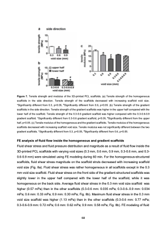
 Figure 7. Tensile strength and modulus of the 3D-printed PCL scaffolds. (a) Tensile strength of the homogeneous scaffolds in the side direction. Tensile strength of the scaffolds decreased with increasing scaffold void size. *Significantly different from 0.3, p<0.05, #Significantly different from 0.6, p<0.05. (b) Tensile strength of the gradient scaffolds in the side direction. Tensile strength of the gradient scaffolds was higher in the upper half compared with the lower half of the scaffold. Tensile strength of the 0.3-0.6 gradient scaffold was higher compared with the 0.3-0.6-0.9 gradient scaffold. *Significantly different from 0.3-0.6 gradient scaffold, p<0.05, #Significantly different from the upper half, p<0.05. (c) Tensile modulus of the homogeneous and the gradient scaffolds. Tensile modulus of the homogeneous scaffolds decreased with increasing scaffold void size. Tensile modulus was not significantly different between the two gradient scaffolds. *Significantly different from 0.3, p<0.05, #Significantly different from 0.6, p<0.05.
FE analysis of fluid flow inside the homogeneous and gradient scaffolds
Fluid shear stress and fluid pressure distribution and magnitude as a result of fluid flow inside the 3D-printed PCL scaffolds with varying void sizes (0.3 mm, 0.6 mm, 0.9 mm, 0.3-0.6 mm, and 0.3- 0.6-0.9 mm) were simulated using FE modeling during 60 min. For the homogeneous-structured scaffolds, fluid shear stress magnitude on the scaffold struts decreased with increasing scaffold void size (Fig. 8a). Fluid shear stress was rather homogeneous in all scaffolds except in the 0.3 mm void size scaffold. Fluid shear stress on the front side of the gradient-structured scaffolds was slightly lower in the upper half compared with the lower half of the scaffold, while it was homogeneous on the back side. Average fluid shear stress in the 0.3 mm void size scaffold was higher (0.57 mPa) than in the other scaffolds (0.3-0.6 mm: 0.035 mPa; 0.3-0.6-.0.9 mm: 0.034 mPa; 0.6 mm: 0.33 mPa; 0.9 mm: 0.30 mPa; Fig. 8b). Maximum fluid shear stress in the 0.3 mm void size scaffold was higher (1.13 mPa) than in the other scaffolds (0.3-0.6 mm: 0.77 mPa; 0.3-0.6-0.9 mm: 0.72 mPa; 0.6 mm: 0.62 mPa; 0.9 mm: 0.58 mPa; Fig. 8b). FE modeling of fluid
68
