
Page 49 - Magnesium-based supports for stem cell therapy of vascular disease - Mónica Echeverry Rendón
P. 49
NOVEL COATINGS FOR COMMERCIAL PURE MAGNESIUM OBTAINED BY PLASMA ELECTROLYTIC OXIDATION THROUGH THE ADDITION OF ORGANIC ADDITIVES
curve is observed, which is characterized by big and bright microdischarges on the sample surface. In this stage, a porous layer is formed as a consequence of a continuous melting and oxidation of the material which have a strong effect on the morphology and topology of the coating. Consequently, during the third stage, the voltage remains in the maximal value for galvanostatic mode and current decrease to the minimal value in potentiostatic mode. This electric behavior is correlated with the increase of the resistance of the coating by the new formed oxide mate- rial. In this stage, the sparks decrease in size and intensity and the voltage and current density remain constant in time. At this point the thickness of the coating can increase with the time of the process [18]. The formation of the coatings under the conditions described previously and the description of the stages of each individual process are summarized in Table.3. In general, for all the evaluated electrolytes, the system was highly stable and with a high reproducibility.
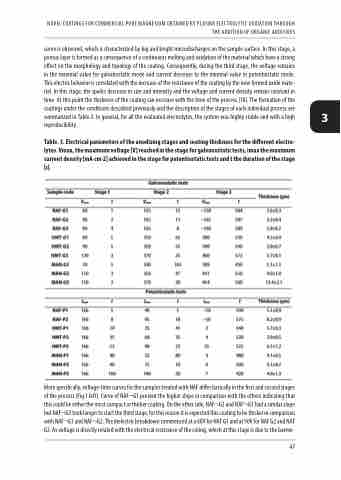
Table. 3. Electrical parameters of the anodizing stages and coating thickness for the different electro- lytes. Vmax, the maximum voltage [V] reached in the stage for galvanostatic tests, imax the maximum current density [mA·cm-2] achieved in the stage for potentiostatic tests and t the duration of the stage [s].
More specifically, voltage-time curves for the samples treated with NAF differ basically in the first and second stages of the process (Fig.1.left). Curve of NAF¬G1 present the higher slope in comparison with the others indicating that this could be either the most compact or thicker coating. On the other side, NAF¬G2 and NAF¬G3 had a similar slope but NAF¬G3 took longer to start the third stage, for this reason it is expected this coating to be thicker in comparison with NAF¬G1 and NAF¬G2. The dielectric breakdown commenced at a 60V for NAF G1 and at 90V for NAF G2 and NAF G3. As voltage is directly related with the electrical resistance of the coting, which at this stage is due to the barrier
3
47
