
Page 48 - Magnesium-based supports for stem cell therapy of vascular disease - Mónica Echeverry Rendón
P. 48
CHAPTER 3
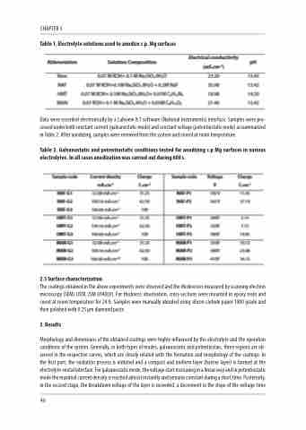
Table 1. Electrolyte solutions used to anodize c.p. Mg surfaces
Data were recorded electronically by a Labview 8.1 software (National Instruments) interface. Samples were pro- cessed under both constant current (galvanostatic mode) and constant voltage (potentiostatic mode) as summarized in Table 2. After anodizing, samples were removed from the system and stored at room temperature.
Table 2. Galvanostatic and potentiostatic conditions tested for anodizing c.p Mg surfaces in various electrolytes. In all cases anodization was carried out during 600 s.
2.3 Surface characterization
The coatings obtained in the above experiments were observed and the thicknesses measured by scanning electron microscopy (SEM) (JEOL JSM 6940LV). For thickness observation, cross-sections were mounted in epoxy resin and cured at room temperature for 24 h. Samples were manually abraded using silicon carbide paper 1000 grade and then polished with 0.25 μm diamond paste.
3. Results
Morphology and dimensions of the obtained coatings were highly influenced by the electrolyte and the operation conditions of the system. Generally, in both types of modes, galvanostatic and potentiostaic, three regions are ob- served in the respective curves, which are closely related with the formation and morphology of the coatings. In the first part, the oxidation process is initiated and a compact and uniform layer (barrier layer) is formed at the electrolyte-metal interface. For galvanostatic mode, the voltage start increasing in a linear way and in potentiostatic mode the maximal current density is reached almost instantly and remains constant during a short time. Posteriorly, in the second stage, the breakdown voltage of the layer is exceeded, a decrement in the slope of the voltage-time
46
