
Page 38 - Synthesis of Functional Nanoparticles Using an Atmospheric Pressure Microplasma Process - LiangLiang Lin
P. 38
Chapter 2
Line 4
Oven
Quartz tube Cathode
MFC MFC
Line 3
MFC MFC
Line 2
MFC
Line 1
Control box
MFC
TiCl4
Electronic Scale
Anode Substrate
Optical fiber
500 Ω
DC power supply
To fume hood
Spectrometer
Computer
N2 H2
Argon
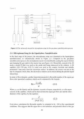
Figure 2.2 The advanced concept the microplasma setup for the gas-phase nanofabrication process 2.1.3 Microplasma Setup for the Liquid-phase Nanofabrication
In the final stage of the project, the microplasma setup was expanded to the liquid-phase nanofabrication, as schematically shown in Figure 2.3. Compared to the gas-phase nanofabrication process, the microplasma reactor was modified by sealing the reactor bottom and changing the gas outlet to the reactor top cap (Figure 2.4). Meanwhile, instead of the SS mesh, a metal Pt disk was used as the anode and being immersed in the solution. A SS capillary (I.D.=318 μm, O.D.=1.6 mm) was used as the counter electrode and initially positioned 1 mm away from the electrolyte surface. In addition, the reactor was put on the top of a magnetic stirrer, thus, the electrolyte solution can be mixed during the plasma-liquid interactions.
In terms of flow dynamic, another important parameter is Reynolds number of the argon gas flow at the operatioal condition, which can be estimated by the formula
Re = rArudin (2.1) μ
Where ρ, μ is the density and the dynamic viscosity of argon, respectively; u is the argon velocity in the capillary, which can be derived from the argon gas flow rate and the inner diameter of the capillary by the equation
u= F (2.2) [p(d 2)2]
From above calculation the Reynolds number is estimated to be ~500 at the experimental conditions. This suggests that the argon flow is not turbulent, and potential effects of the gas
26
-+
