
Page 36 - Synthesis of Functional Nanoparticles Using an Atmospheric Pressure Microplasma Process - LiangLiang Lin
P. 36
Chapter 2
2.1 Multiphase Operational Microplasma Setup
In the present research a DC-driven microplasma setup was built up for the synthesis of nanomaterials, of which the operational space has been gradually expanded with the progress of the project. The evolution of the plasma setup can be briefly divided into 3 stages (shown below), while the detailed images of the setup can be referred to the Supplementary Material Figure S1 and Figure S2.
2.1.1 Initial Concept of the Microplasma Setup for the Gas-phase Nanofabrication
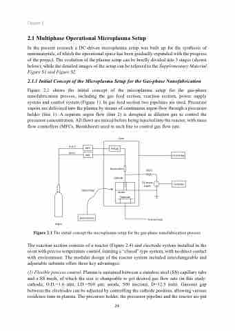
Figure 2.1 shows the initial concept of the microplasma setup for the gas-phase nanofabrication process, including the gas feed section, reaction section, power supply system and control system (Figure 1). In gas feed section two pipelines are used. Precursor vapors are delivered into the plasma by means of continuous argon flow through a precursor holder (line 1). A separate argon flow (line 2) is designed as dilution gas to control the precursor concentration. All flows are mixed before being injected into the reactor, with mass flow controllers (MFCs, Bronkhorst) used in each line to control gas flow rate.
Line1
Oven
Quartz tube Cathode
Line2
MFC
Argon
MFC
Optical fiber
500Ω
DCpower supply
To fume hood
Fe(Cp)2
Spectrometer
Figure 2.1 The initial concept the microplasma setup for the gas-phase nanofabrication process
The reaction section consists of a reactor (Figure 2.4) and electrode system installed in the oven with precise temperature control, forming a “closed” type system, with no direct contact with environment. The modular design of the reactor system included interchangeable and adjustable subunits offers three key advantages:
(1) Flexible process control. Plasma is sustained between a stainless steel (SS) capillary tube and a SS mesh, of which the size is changeable to get desired gas flow rate (in this study: cathode, O.D.=1.6 mm, I.D.=500 μm; anode, 500 microns, D=12.5 mm). Gaseous gap between the electrodes can be adjusted by controlling the cathode position, allowing various residence time in plasma. The precursor holder, the precursor pipeline and the reactor are put
24
Control box
Computer
Anode Substrate
-+
