
Page 66 - Development of Functional Scaffolds for Bone Tissue Engineering Using 3D-Bioprinting of Cells and Biomaterials - Yasaman Zamani
P. 66
This compressive force gradually decreased from top-to-bottom of the scaffold until it reached zero, and then it transformed into a tensile force of 107.5 N in the lower rim of the scaffold (equation 5, Fig. 3c):
total transverse force in the lower rim of the scaffold = force along the y-axis + torque around the x-axis
= 127.5 + (-235) = -107.5 N (tensile). (5)
Microstructure of homogeneous and gradient scaffolds
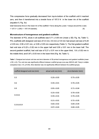
The diameter of PCL struts in all scaffolds was 0.71 ± 0.05 mm (mean ± SD; Fig. 4a, Table 1). PCL scaffolds with designed void size of 0.3 mm, 0.6 mm or 0.9 mm had actual void size of 0.20 ± 0.03 mm, 0.59 ± 0.01 mm, or 0.95 ± 0.05 mm respectively (Table 1). The first gradient scaffold had void size of 0.23 ± 0.02 mm in the upper half and 0.59 ± 0.01 mm in the lower half. The second gradient scaffold, had void size of 0.21 ± 0.01 mm in the upper third, 0.6 ± 0.02 mm in the middle third, and 0.97 ± 0.03 mm in the lower third (Fig. 4b; Table 1).
Table 1. Designed and actual void size and strut diameter of 3D-printed homogeneous and gradient scaffolds (mean ± SD, n=5). The void size was significantly different between scaffold groups (one-way ANOVA with Tukey’s multiple comparison test, n=5, p<0.05). Strut diameter was not significantly different between the scaffold groups.
scaffold designed void size (mm)
actual void size (mm) strut diameter (mm)
0.3 0.6 0.9
0.3-0.6 0.3-0.6-0.9
0.20 ± 0.03 0.59 ± 0.01
0.95 ± 0.05
0.23 ± 0.02 0.59 ± 0.01
0.21 ± 0.01 0.60 ± 0.02 0.97 ± 0.03
0.73 ± 0.05 0.70 ± 0.05
0.71 ± 0.04
0.70 ± 0.03 0.70 ± 0.05
0.72 ± 0.05 0.69 ± 0.04 0.69 ± 0.05
64
