
Page 85 - Tailoring Electrospinning Techniques for Regenerative Medicine - Marc Simonet
P. 85
TAILORING THE VOID SPACE AND MECHANICAL PROPERTIES IN ELECTROSPUN SCAFFOLDS
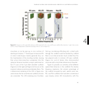
Figure 4.3 Comparison of the spatial fiber distances (SFD) obtained for the conv. and LTE spun sca olds (fiber diameter = 9 μm). Cubic inserts 4 are the corresponding distance transformed analogs of the CT scans in Figure 4.2.
one plane, as can be seen e.g. in cross sections of electrospun meshes.10,23 Techniques to measure SFD or voids in electrospun meshes generally focus on the maximization of the resulting number, leaving their actual interconnections unexplored. Also the spherical distance transform analysis performed on the CT scans of the 9 μm fiber diameter sca olds (Figure 4.2 on the right and Figure 4.3) focuses on the maximal 3 dimensional distance between fibers. The 3 dimensional rendering of the SFD in Figure 4.2a and b shows that for conventional sca olds all voids are connected. This SFD rendering also illustrates
that e.g. considering infiltrating cells, a direct path through the sca old could be blocked by sca old fibers or an interconnection much smaller than the two adjacent voids. In contrast, LTE spun sca olds (Figure 4.2c and d) feature fully interconnected structures with a truly three-dimensional character.
Figure 4.3 provides an overview of the di erent spatial fiber distances in the sca olds The relative frequency represents the volume percentage of the sca old occupied by each specific pore size. PCL and PLA sca olds that had been conventional spun display similar SFD characteristics with the
83
