
Page 61 - Development of Functional Scaffolds for Bone Tissue Engineering Using 3D-Bioprinting of Cells and Biomaterials - Yasaman Zamani
P. 61
microstructure of homogeneous and gradient-structured scaffolds was visualized using a Nikon SMZ-10 stereo microscope (Nikon, Tokyo, Japan).
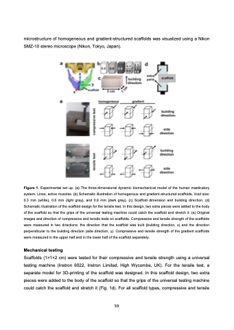
Figure 1. Experimental set up. (a) The three-dimensional dynamic biomechanical model of the human masticatory system. Lines, active muscles. (b) Schematic illustration of homogenous and gradient-structured scaffolds. Void size: 0.3 mm (white), 0.6 mm (light gray), and 0.9 mm (dark gray). (c) Scaffold dimension and building direction. (d) Schematic illustration of the scaffold design for the tensile test. In this design, two extra pieces were added to the body of the scaffold so that the grips of the universal testing machine could catch the scaffold and stretch it. (e) Original images and direction of compressive and tensile tests on scaffolds. Compressive and tensile strength of the scaffolds were measured in two directions: the direction that the scaffold was built (building direction, x) and the direction perpendicular to the building direction (side direction, y). Compressive and tensile strength of the gradient scaffolds were measured in the upper half and in the lower half of the scaffold separately.
Mechanical testing
Scaffolds (1×1×2 cm) were tested for their compressive and tensile strength using a universal testing machine (Instron 6022, Instron Limited, High Wycombe, UK). For the tensile test, a separate model for 3D-printing of the scaffold was designed. In this scaffold design, two extra pieces were added to the body of the scaffold so that the grips of the universal testing machine could catch the scaffold and stretch it (Fig. 1d). For all scaffold types, compressive and tensile
59
