
Page 66 - Magnesium-based supports for stem cell therapy of vascular disease - Mónica Echeverry Rendón
P. 66
CHAPTER 4
2.2 Anodization of the samples
Anodization set up consisted of an electrolytic cell where the Mg sample was used as anode and a stainless-steel beaker containing the electrolytic solution was used as cathode and connected to a DC power supply (Kepco BHK 500-0.4 MG). The base electrolytic solution consisted of sodium metasilicate (0.1 M Na2SiO3.9H2O) and potassium hydroxide (0.07 M KOH). Three different additives were evaluated; one commonly used i.e. inorganic sodium fluo- ride (0.2M, NaF) and two compounds, hexamethylenetetramine (HMT) and mannitol (MAN) never studied in this context. Samples anodized in NaF were operated at galvanostatic mode and for HMT and MAN potentiostatic mode was used. In table 1 the operational parameters are summarized.
Table 1. Conditions tested for anodizing c.p Mg surfaces in various electrolytes. In all cases anodiza- tion was carried out during 600 s.
In addition, samples were processed using a two-step anodizing process as shown in Table 2. First, in presence of NAF at galvanostatic mode and after that, a second anodizing was performed in an electrolytic solution containing either HMT or MAN at potentiostatic mode. This approach was derived from the hypothesis that the first relatively thin layer made in a NAF electrolyte could offer corrosion protection, as it is well known the passivation ability of this additive for Mg surfaces. Therefore, this layer could facilitate the formation of a thicker layer and consequently a better surface protection will be obtained. After anodizing, samples were removed from the system and stored at room temperature.
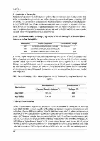
Table 2: Parameters employed to form the two-steps anodic coatings. Both anodization steps were carried out dur- ing 600 s.
2.3 Surface characterization
Surface of the obtained coatings and its respective cross sections were observed by scanning electron microscopy (SEM) (JEOL JSM 6940LV). Chemical composition of the coatings was analyzed by energy dispersive spectroscopy (EDS) and by X-ray diffraction (XRD) by using a X-Pert Philips PW 3040/60 instrument with Cu Kα radiation with a scan range in 2θ from 20° to 90o. Grazing incidence X-ray diffraction (GIXD) patterns were taken with a 0.05° step at an incident angle α of 2°. The phases present in the coatings were identified in the HighScore Plus software by comparison with data in the ICSD database. Topography and surface morphology were assessed by using atomic force microscopy (AFM) (MFP-3D Infinity, Asylum Research). Areas of 50×50 μm were scanned in contact mode at a rate of 0.3 Hz, using a TR400PB tip (tip radius 42 nm, spring constant of 0.1). To quantify surface roughness, average amplitude in the height direction were measured at different points with respect of the central line. Some of the most commonly reported
64
