
Page 23 - Synthesis of Functional Nanoparticles Using an Atmospheric Pressure Microplasma Process - LiangLiang Lin
P. 23
Introduction - Plasma and Microplasma-assisted Nanofabrication
4) Microplasma-liquid systems
In past decades, with the development of nanoscience and the emergence of microplasma- liquid systems, an obvious question was naturally raised: Can charged radicals be transferred between plasmas and electrolytes to enable electrochemical reactions and produce nanomaterials of controlled properties? 81 The pursuit of the answer to this question attracted enormous academic research from different fields to investigate this fascinating concept. Till now various microplasma-liquid systems have been designed and explored for the synthesis of nanomaterials. Based on whether the plasma contacts the liquid or not, the microplasma- liquid systems can be divided into two categories: indirect contact plasma-liquid systems and direct contact plasma-liquid systems.
Indirect contact plasma-liquid systems refer to the configurations where plasmas are formed in the gas phase above the solution surface. Usually one electrode is in the form of “pin” or with a sharp “edge” and put in the gas phase within a distance of 2 mm above the liquid electrolyte, while the other electrode is immersed inside the electrolyte and can be in various shapes. Power supplies of different frequencies ranging from dc, kHz, MHz and even to GHz are coupled on the electrodes to excite and sustain the plasma.82 In this sense the discharge is generated between the upper electrode and the electrolyte surface, and the precursors dissolved in the electrolyte will be reduced to form nanomaterials by electrons under the plasma treatment. With few exceptions which involving ionic liquids, such plasma systems are operated at atmospheric pressure or higher.83,84
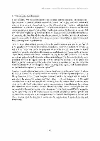
A typical example of the indirect contact plasma-liquid system is shown in Figure 1.5, where the HAuCl4 solution (0.2 mM) was used as the electrolyte to produce gold nanoparticles.85 A SS capillary tube (I.D.= 175 μm, Length= 5 cm) was used as the cathode and positioned 2 mm above the electrolyte surface. A Pt foil (Area = 1×1 cm2, thickness = 0.001 inch) functioned as the anode and was placed 3 cm away from the cathode. Both electrodes were connected to a DC high voltage power supply, and plasma was formed between the capillary tube and the electrolyte surface. For each operation a helium flow of 25 sccm gas flow rate was coupled to the capillary acting as the plasma gas. A 10 ml solution of HAuCl4 was put in a petri dish, with a 0.01 M fructose added to prevent uncontrolled particle growth and agglomeration. Meanwhile, processing parameters such as solution temperature, current, and rate of stirring could be adjusted to synthesize Au nanoparticles of controllable size and morphology.
11
